
Environmental Barrier System: Geosynthetic Solutions for Modern Environmental Protection and Design
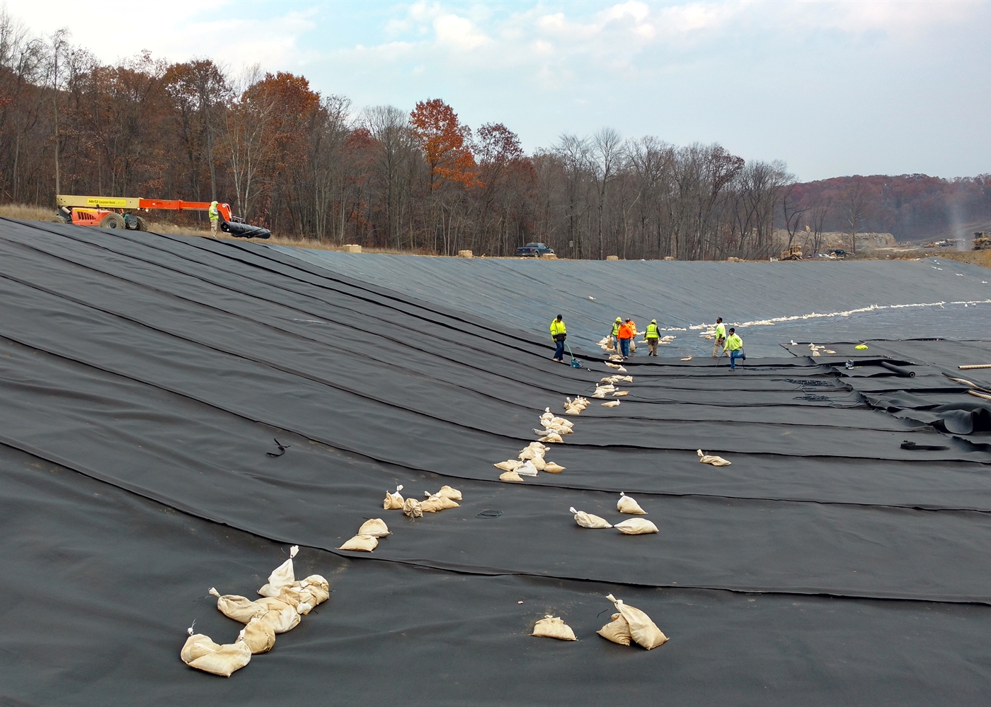
Table of Contents
An environmental barrier system is the engineered assembly that protects soil and groundwater from contaminant migration, controls fluid movement, and supports gas collection and resource recovery at waste and industrial sites. This article is a practical, engineer-focused guide to planning, specifying and delivering robust geosynthetic systems for landfill liners, leachate collection, containment basins and secondary containment applications. It is written for overseas engineers and owners who require verifiable performance, predictable construction outcomes and clear long-term monitoring commitments.
Executive summary
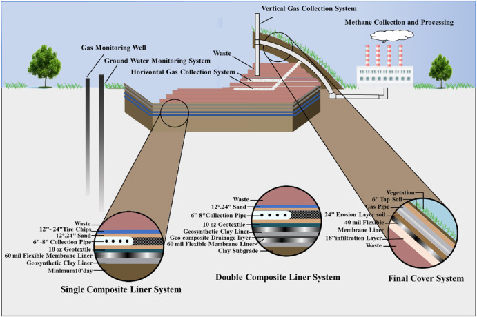
A properly designed environmental barrier system integrates multiple layers—primary geomembrane, geosynthetic clay liner (GCL) or compacted clay, geocomposite drainage, leak detection and protective cover—to deliver measurable performance over the design life. The combined system minimizes leakage, reduces hydraulic head on liners and simplifies monitoring and maintenance. When regulators and auditors review a project, they expect the environmental barrier system design to lock in material performance targets, construction quality assurance (CQA) protocols and a documented operations plan.
Why adopt a system approach?
Shifting from single-product delivery to an engineered environmental barrier system focuses procurement and construction on outcomes rather than components. The system approach aligns designers, suppliers, contractors and operators around shared acceptance criteria, lowering the likelihood of disputes and reducing rework. Practically, a system mindset ensures the environmental barrier system is verified by testing, documented by CQA and maintained through a realistic O&M plan.
Core components and their roles
1.Primary liner — HDPE geomembranes and GCLs
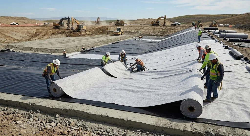
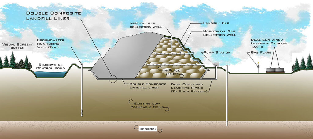
The primary liner forms the core of an environmental barrier system. A composite of HDPE geomembrane over a geosynthetic clay liner (GCL) is commonly used where footprint constraints demand very low permeability. Specify HDPE thickness according to site-specific puncture and loading risks, and require supplier long-term aging data. In many jurisdictions, EPA technical reviews and state guidance (e.g., Washington State Department of Ecology) are referenced to define acceptable performance baselines for composite liners; incorporate those baseline expectations into the environmental barrier system procurement documents.
2.Leachate collection and removal system (LCRS)
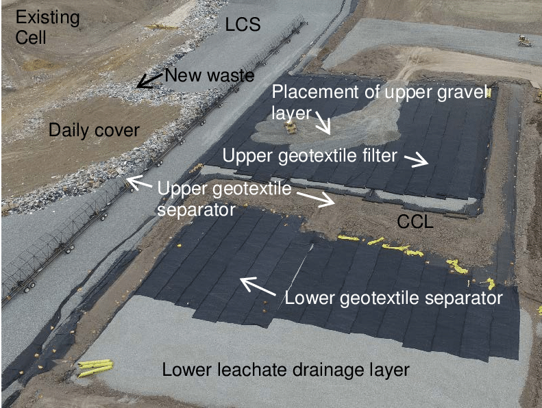
A functioning LCRS prevents an increase in hydraulic head that could compromise the liner. The LCRS is therefore a critical element of any environmental barrier system. Use geocomposite drainage or high-transmissivity geonets sized for expected solids loading, and include accessible sumps and cleanouts. State guidance documents (for example, Oregon DEQ LCRS recommendations) stress the importance of cleanout access, transmissivity testing and routine maintenance to ensure the environmental barrier system performs under service conditions.
3.Leak detection and monitoring layers
Credible leak detection is a staple of an environmental barrier system. Options include a dedicated low-permeability detection layer with monitoring ports or a monitored secondary drainage layer that will reveal anomalous flows. Define sampling frequency, alarm thresholds and remedial actions in the technical specification so the system owner and operators can respond to early warning signals without ambiguity.
4.Secondary containment and emergency systems
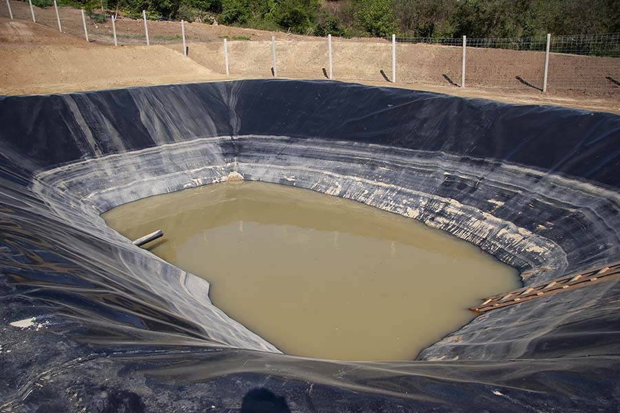
Where hazardous liquids or solvents are stored, a secondary containment module supplements the environmental barrier system by providing immediate spill capture, segregation and rapid response paths. The secondary system must be specified for the chemical classes present; seam practices, compatibility testing and a validated spill response procedure should be part of the contract.
5.Gas collection and resource recovery
Designing gas management into the closure and cover strategy adds value—both environmental and economic—to the environmental barrier system. Integrate gas-collection layers and vertical wells so methane and other gases can be safely collected for flaring or energy recovery. Industry guidance and landfill gas design manuals emphasize early integration of gas infrastructure to avoid costly retrofits and to maximize capture efficiency over the post-closure period.
Material selection and verification
aterial selection sets the practical performance of the environmental barrier system. Use a matrixed approach that cross-references chemical compatibility, mechanical properties, installation risks and verified test results. Require factory QA documentation, traceable lot numbers and representative sample testing on delivery. For example, geomembrane buy-offs should include melt index, carbon black content and tensile/puncture results; GCL selection should reference bentonite content, swell potential and shear tests. Where applicable, align these requirements with recognized industry specifications so the environmental barrier system is defensible in regulatory review.
Construction quality assurance (CQA)
A rigorous CQA program turns design intent into demonstrated performance for the environmental barrier system. Essential elements include pre-installation subgrade verification, witnessed geomembrane welding with non-destructive seam testing, documented GCL placement and anchorage checks, and in-place transmissivity verification for drainage composites. Require third-party CQA signoffs at prescribed milestones; documented CQA reduces later liability and shortens acceptance cycles.
Operations, maintenance and monitoring
Lifecycle success depends on a practical O&M strategy for the environmental barrier system. Define monitoring frequency for leak detection ports, leachate sump checks, pump testing and gas extraction optimization. Establish action thresholds and an escalation matrix so that anomalies prompt measured interventions rather than ad hoc drilling. Maintain O&M logs as part of the compliance package; these logs serve both regulators and future site owners.
Typical specification clauses
To avoid ambiguity in procurement, include clear clauses that describe the minimum acceptable performance of the environmental barrier system:
- Supplier data sheets and factory QA records must be provided and linked to lot traceability.
- Geomembrane minimum thickness, seam strength and long-term aging criteria shall be specified numerically.
- GCL composition, bentonite content and hydration behavior shall be defined and tested.
- LCRS layout shall include manhole spacing, sump capacities and cleanout access.
- CQA provider scope and mandatory inspection checkpoints must be contracted prior to construction.
Incorporating this contract language reduces interpretation risk and aligns contractor deliverables with the environmental barrier system performance targets.
Regulatory alignment and practical references in the field
Regulators and technical reviewers commonly expect designers to reference established guidance when defining the environmental barrier system. State and federal technical reviews on geosynthetics, LCRS design guidance and landfill gas manuals provide practical test methods and acceptance thresholds—use those guidance documents to form the technical backbone of your specification. Project teams that explicitly tie performance criteria to those sources find the permitting and approval path smoother.
Conclusion
Successful projects treat geosynthetic protection as an integrated environmental barrier system, not simply as an inventory of products. By combining careful material selection, strong CQA, explicit contract language and a practical O&M program, owners can achieve verifiable performance, regulatory acceptance and lower lifecycle risk. Designing with those priorities in mind delivers an implementable, maintainable and auditable barrier solution for modern environmental protection needs.
If you want to know more about the relevant content, please click here.