
Geomembrane Thickness & Design Guide: Engineering Standards for Wastewater
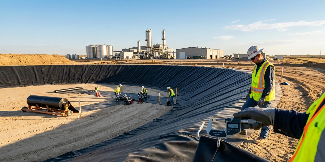
In the high-stakes world of environmental containment, the margin for error is non-existent. Selecting the appropriate geomembrane thickness is the single most critical decision an engineer makes during the planning phase. Whether you are lining a municipal sewage lagoon or a complex industrial effluent pond, the liner serves as the final barrier between hazardous waste and the groundwater table.
A common misconception in the B2B sector is that simply increasing the gauge always leads to a better project outcome. In reality, over-specifying creates unnecessary material costs and installation friction, while under-specifying leads to catastrophic puncture failures. Therefore, a data-driven geomembrane thickness strategy is essential for project longevity.
Table of Contents
Understanding Geomembrane Gauge and Measurement Units
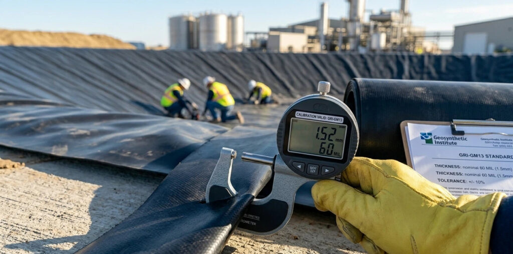
Before diving into the geomembrane thickness calculation wastewater professionals require, we must clarify the terminology. In international markets, thickness is typically measured in millimeters (mm) or mils (1/1000 of an inch).
For example, a standard 60-mil liner is approximately 1.5 mm thick. Accuracy in defining the geomembrane thickness is essential for international procurement, as ASTM standards often use mils while ISO standards favor metric units. Miscommunication here can result in material that fails to meet the mechanical properties defined in your geomembrane design guide.
The geomembrane gauge you choose must align with the specific stress-strain parameters of your containment site.
Key Factors Influencing Design Selection
The process to design geomembrane systems begins with a site-specific risk assessment. Several physical and chemical factors dictate the minimum required geomembrane thickness
- Subgrade Condition: If the subgrade contains sharp stones or uncompacted debris, the liner requires a higher puncture resistance.
- Liquid Pressure: In deep wastewater ponds, the hydrostatic pressure at the base can be immense.
- Chemical Concentration: Aggressive industrial chemicals can cause polymer degradation over time.
- UV Exposure: For exposed liners in sewage lagoons, UV radiation accelerates oxidative induction time (OIT) loss.
Recommended Standards for Sewage Lagoons
For municipal projects, the recommended geomembrane thickness sewage lagoon standard typically starts at 1.0 mm (40 mil) for HDPE. However, most modern environmental protection agencies now lean toward 1.5 mm (60 mil) as the industry benchmark for primary containment.
The reason for this shift is “weldability.” A 60-mil geomembrane thickness provides a more robust area for double-track fusion welding. This ensures that the seams—the most vulnerable part of any lining system—are as strong as the parent material. When you design geomembrane layouts for municipal waste, you must ensure the geomembrane thickness (6) accounts for potential settlement over a 20-year service life.
| Application Type | Recommended Thickness (mm) | Recommended Gauge (mil) | Primary Engineering Benefit |
| Temporary/Secondary Containment | 0.75 mm | 30 mil | High flexibility; lower material cost. |
| Standard Municipal Sewage Lagoon | 1.0 mm | 40 mil | Basic puncture resistance; standard compliance. |
| Industrial Effluent & Heavy Duty | 1.5 mm | 60 mil | Optimal weldability; superior stress-crack resistance. |
| High-Risk Sludge & Deep Ponds | 2.0 mm | 80 mil | Maximum physical protection; handles high point loads. |
Technical Foundations: Stress and Calculation
To perform a precise geomembrane thickness calculation wastewater engineers use theconcept of allowable stress versus actual stress. The material must be sufficient to resist thetension (T) generated by the weight of the liquid and the slope of the pond.
A simplified engineering formula for tension in an anchored liner is:
T=p.R
Where:
- T = Tension per unit width
- p = Pressure exerted by the liquid
- R = Radius of the curvature of the subgrade deformation
If the calculated tension exceeds the allowable yield strength, the geomembrane thickness must be increased accordingly. Most high-density polyethylene (HDPE) designs incorporate a factor of safety (FoS) of at least 2.0 to 3.0 to account for thermal expansion and contraction.
Industrial Sludge Ponds and High-Density Applications
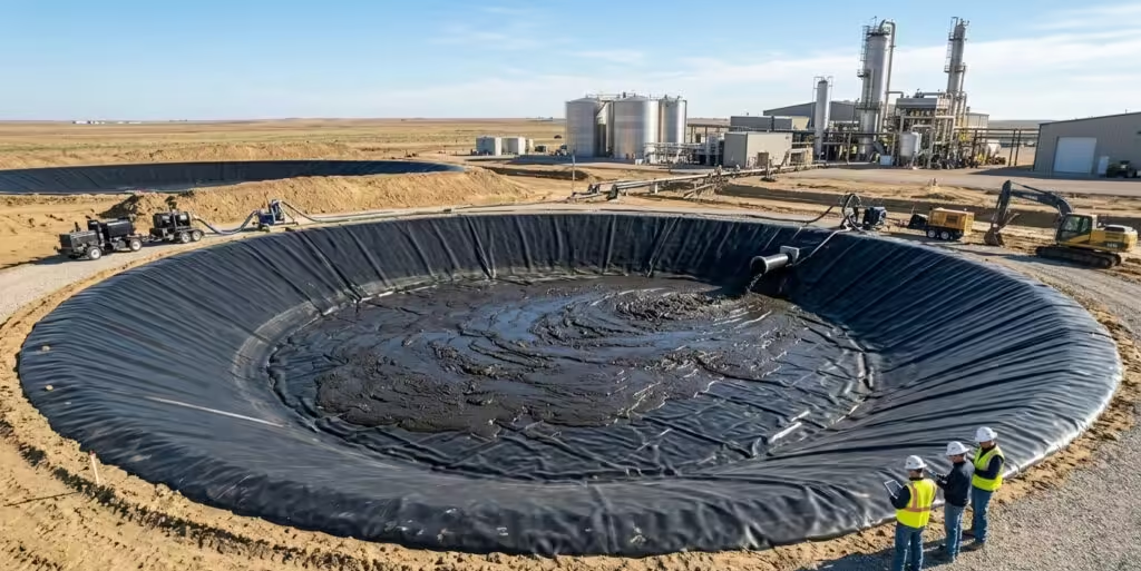
Sludge ponds present a unique challenge because the material is often abrasive and dense. In these scenarios, the geomembrane thickness often moves into the 2.0 mm (80 mil) or 2.5 mm (100 mil) range.
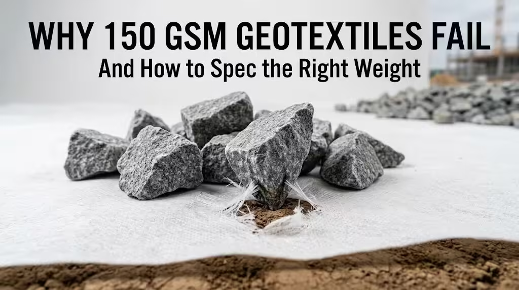
Puncture resistance becomes the primary design variable here. Unlike clear water, sludge can hide sharp objects or heavy sediments that exert significant point loads. Referring to a technical geomembrane design guide will help determine if a protective geotextile cushion is needed beneath the membrane to supplement the barrier.
Global Standards and Compliance (ASTM & GRI)
Compliance with international standards is what separates professional engineering from guesswork. Any reputable geomembrane thickness specification should reference the GRI-GM13 standard for HDPE or GRI-GM17 for LLDPE.
- ASTM D5199: The standard test method for measuring the nominal thickness of geosynthetics.
- GRI-GM13: This standard dictates that the lowest individualgeomembrane thickness measurement must not be more than 10% below the nominal value.
By citing these standards, your project documentation ensures that the material provided by the manufacturer is consistent across every roll delivered to the site.
Installation Realities: Welding and Seaming
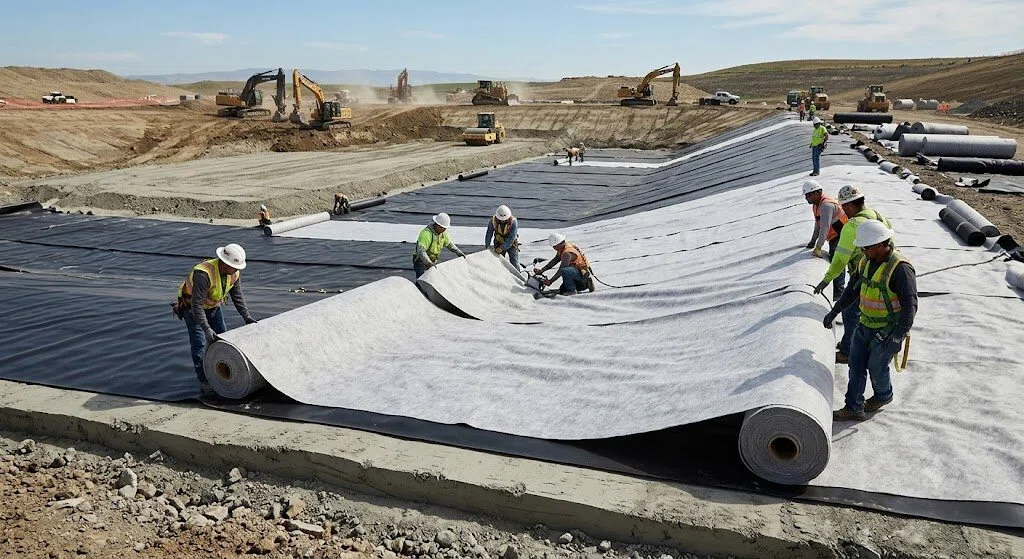
A technical geomembrane design guide isn’t just about the finished product; it’s about the installation process. Thinner membranes (under 0.75 mm) are prone to “burn-through” during fusion welding. Conversely, an excessively high geomembrane thickness requires higher heat and slower speeds, which can degrade the polymer structure at the seam if not managed correctly.
Maintaining a consistent profile allows the installation team to calibrate their welding equipment once, ensuring uniform seam strength across the entire wastewater facility.
Conclusion
Choosing the right profile is a balance of engineering physics and economic reality. For wastewater and industrial containment, the risks of failure far outweigh the initial savings of a thinner geomembrane thickness.
By following a data-driven geomembrane design guide, calculating specific stress loads, and insisting on GRI-compliant materials, you ensure a containment system that protects the environment for decades. Consistency in your technical specifications is the hallmark of a high-quality industrial project.
FAQ
Is 1.0 mm (40 mil) thick enough for an industrial wastewater pond?
Generally, no. While 1.0 mm might work for decorative ponds, an industrial application usually requires at least 1.5 mm (60 mil) to handle chemical exposure and installation stresses.
Does a higher gauge help with UV resistance?
Indirectly. While UV resistance is determined by carbon black content, a thicker liner has more sacrificial material, meaning it takes longer for oxidative degradation to impact the core.
How do I verify the geomembrane gauge on-site?
Use a calibrated digital micrometer per ASTM D5199. Measurements should be taken at regular intervals across the width of the roll.
What is the most common mistake in geomembrane design?
Ignoring the subgrade. If the subgrade is poor, even the highest quality material cannot prevent a puncture. Always prioritize subgrade preparation alongside material selection.